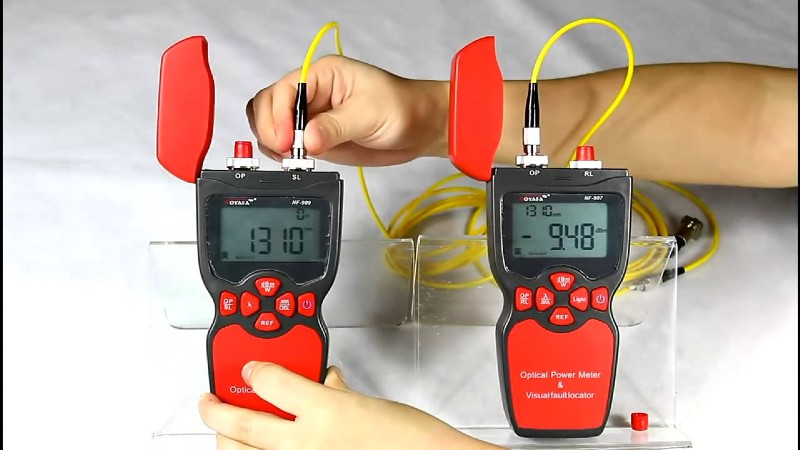
Many of the issues encountered when connecting fibre optic networks are connected to making suitable connections. The system transmitter light cannot be seen because the light utilised in systems is invisible infrared light (IR) that is beyond the range of the human eye.
A visible light source (incandescent bulb, LED, or laser diode) that injects visible light energy into a fibre is known as a Visual Fault Identifier (VFI) or Visual Fault Locator (VFL).
By infusing light from a visible source, the fibre may be visually traced from transmitter to receiver to confirm proper orientation and continuity.
Sharp bends, breaks, bad couplings, and other flaws will “leak” the light, allowing professionals to detect the flaws visually.
How should a fibre optic visual fault finder be used?
A visual fault locator emits a powerful beam of red light that may be seen from a long distance. Connect it to one end of a fibre and then find that fibre at the other end, even whether it’s one of many fibres in a cable or terminated in a rack.
Simple end-to-end continuity checks should be performed. Check the polarity and orientation of fibres within a multi-fiber connector such as the MT-RJ.
A visual fault locator can instantly reveal fibre breaks, damaged patch cord connectors, faulty splices in splice trays, and tight fibre bends in and around equipment racks.
The built-in universal 2.5mm adaptor allows for simple connection to SC, ST, FC, and FJ connectors. Connection to LC and MU connections is possible with the optional 1.25mm adaptor.
Important VFL parameters: How to Select the Best Visual Fault Locators
Distance between fibres
The fibre distance specification specifies the longest fibre length at which the leakage light may be seen without difficulty. The laser light power determines this spec. The industry standard specification for multimode fibres is 10km, whereas for single mode fibres it is 5km. The FS high power 30mW fibre optic fault locator has a dynamic range of up to 15km.
Output power is a crucial specification for visible fault indicators. Some may wonder how much power I require. The crucial point is that the higher the output power, the longer the fibre distance it can handle. This specification is typically 0.5mW connected to single mode fibres and 2mW to free space (no fibre coupling, just the light output from the tester’s connection adaptor).
The fibre mode
All visual fault locators are capable of working with single mode and multimode fibres. Because multimode fibre contains a 50um or 62.5um core, which is substantially larger than the 9um core of single mode fibre, more light power can be coupled into multimode fibres. This means that multimode fibres have a greater fibre distance than single mode fibres.
Frequency of modulation (CW and 2Hz)
Human eyes are far more sensitive to blinking light than they are to constant light. As a result, visual fault locators are available in two operating modes: continuous wave and pulse light. Most fibre optic installation professionals choose the pulse light mode, which turns the laser source on and off at a frequency of 2Hz or 1Hz.
Battery
Two AAA or two AA alkalescency batteries are typically used.
Wavelength
Wavelength is not a crucial specification. 635nm, 650nm, and 670nm are all valid wavelengths.
A pulsed output is produced by pulsed fibre optic fault locators. This allows fibre optic identifiers to distinguish between fibres based on tone. Fiber optic instrument locators that are pocket-sized are designed to fit into a pocket. They are also known as pen size. The operating temperature is an important environmental characteristic to consider for fibre optic fault locators.


